Healing Defective Traces
On some occasions, the reduction recipe responsible for determining the spectral traces does not work correctly. This may be due to slight detector defocus and/or low signal at one of the ends of the observed spectral range. If the problem does not occur in too many fibers, we describe here a manual procedure that allows obtaining corrected traces for the poorly adjusted fibers, using the information from well-adjusted neighboring traces.
Note
Sometimes the problem is that we do not have an adequate trace file. For example, when using the VPH LR-U valid traces are not obtained for most of the fibers. In such cases, it is an excessive effort to manually fix the adjustment for each fiber. The best alternative is to reuse an existing trace file and try to transform it for the exposures we need to calibrate. At the end of this page, in the Obtaining traces for LR-U section, we show an example of how to do this.
Identifying defective traces
Following the instructions in Section Tracing fibers, we look at the reduction step where the traces are determined, e.g.
(megara) $ numina run 1_tracemap.yaml
Please note that the execution of the last command has generated an on-screen output indicating that the traces of some fibers have encountered issues. Specifically, the affected fibers are: 603, 604, 606, 607, 610, and 614.
Move to the subdirectory with the results from the previous step.
(megara) $ cd obsid1_LR-R_tracemap_results/
Identifying faulty traces is straightforward using the
megaradrp-overplot_traces script.
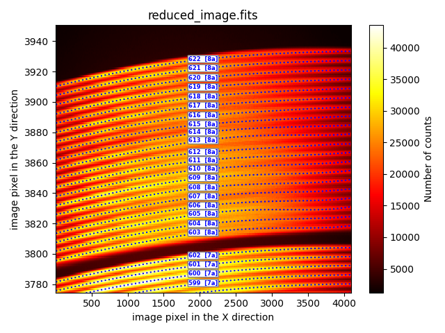
(megara) $ megaradrp-overplot_traces reduced_image.fits master_traces.json
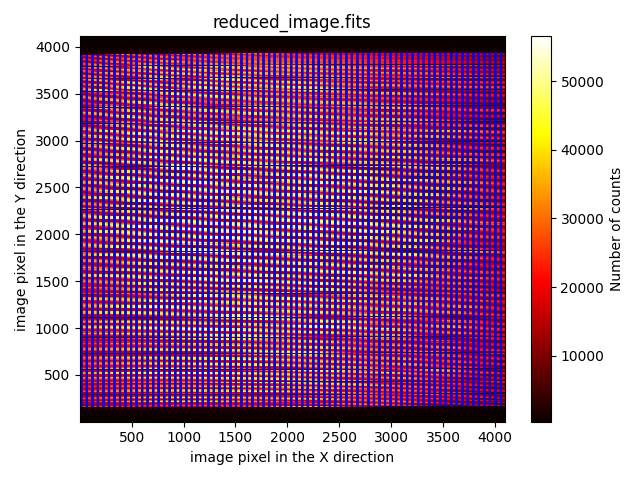
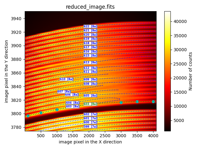
Although the traces appear to be correctly calculated, when zooming in on the
fibers corresponding to Box 8a, we can see that there are several fibers
whose traces have not been calculated correctly. We can zoom in on the
matplotlib image using the magnifying glass tool, or we can run the previous
script using the --bbox parameter, which takes a list with 4 numbers (xmin,
xmax, ymin, ymax). We also add the --fibids parameter, which enables
displaying the fiber number in the same figure.
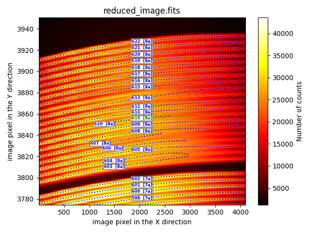
(megara) $ megaradrp-overplot_traces reduced_image.fits master_traces.json \
  --fibids \
  --bbox 1,4096,3775,3950

The trace signal fades for X values around the range [2500, 3500], causing some traces to end prematurely (fibers 603, 604, 606, 607, 610), to switch fibers (e.g., the trace for fiber 613 jumps to the position of fiber 614), or even for the trace to fail to be calculated (fiber 614). Not surprisingly, these are the same fibers with issues in the execution of the MegaraTraceMap recipe.
The next section describes the different strategies that can be employed to fix wrong (or even missing) traces.
Strategies to fix defective traces
The megaradrp-heal_traces script helps recover miscalculated traces using
different options. An example of execution is as follows:
(megara) $ megaradrp-heal_traces reduced_image.fits master_traces.json \
  --fibids --healing healing.yaml \
  --updated_traces master_traces_healed.json
The first two parameters are the same as those used with the
megaradrp-overplot_traces script (the FITS image and the JSON file with
information about the calculated traces). The new relevant parameters are:
--healing <healing.yaml>: specifies the name of a YAML file that defines the strategy for correcting erroneous traces. The format of this file is explained in more detail below.--updated_traces <master_traces_healed.json>: specifies the name of the JSON file that will store the corrected version of all traces.
With the help of the <healing.yaml> file, we can make use of different
strategies to correct faulty traces. These strategies are indicated in the
YAML file using the tag description.
The corrections to be applied to calculate the new trace for each fiber are
included in the YAML file in independent blocks separated by the usual YAML
separator --- (see a more detailed example in the next section).
Next we show the different possibilities with some example numbers.
sandwhich
Useful for defining a trace using information from two neighboring traces.
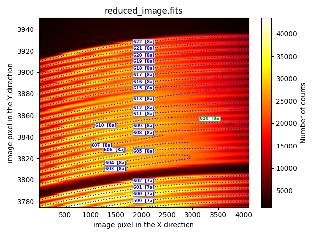
description: sandwich
fibid: 610
fraction: 0.5
neighbours: [609, 611]
xstart: 6
xstop: 4090
In the example, the corrected trace for fibid: 610 (green dotted line) is
calculated halfway between the position of the trace for fiber 609 and fiber
611. The fraction tag equal to 0.5 indicates that the new trace is
equidistant from the other two. This fraction number can be varied to obtain
traces that are not equidistant from the two reference traces. For example,
fraction=0.33333 would make the new trace one-third of the distance from the
first fiber indicated in the tag neighbors. The xstart and xstop
tags indicate the X coordinate where the new trace will be valid.
extrapolation
This method enables the extrapolation of traces whose fitting is truncated on the X-axis.
description: extrapolation
fibid_ini: 610
fibid_end: 610
xstart: 6
xstop: 4090
In this approach, the fibers whose numbers are between fibid_ini and
fibid_end are recomputed for X-axis values in the interval [xstart,
xstop]. It is also possible to indicate a list of fibers using the tag
fibid_list instead of the pair of tags fibid_ini and fibid_end.
In the example shown, only the initial fitting performed for fiber 610 (blue dotted line) has been extrapolated. It can be observed that the result (green dotted curve) is not optimal. It is likely that a simple extrapolation of the initially performed fitting will not be a good estimation of the trace in the regions where it has not been possible to determine the trace position. In general, it will be more useful to use the method described below.
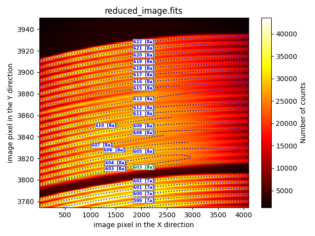
extrapolation_through_user_points
This method offers a much more reliable extrapolation strategy because the user can define a set of additional points that are also used to fit the trace.
description: extrapolation_through_user_points
fibid: 603
xstart_reuse: 4
xstop_reuse: 2000
resampling: 20
poldeg: 5
xstart: 6
xstop: 4090
user_points:
  - [3500, 3817.0]
  - [4000, 3818.0]
refit: False
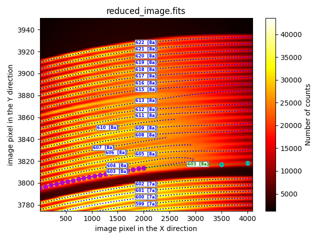
In the example shown, the extrapolation of the initial fitting for fiber 603
(blue dotted line) has been performed reusing the prediction of this initial
fitting in the interval [xstart_reuse, xstop_reuse]. The resampling
parameter indicates that 20 intermediate points (magenta filled circles) are
calculated within this interval, which constitute the data that are actually
used in the new fitting. In addition to these 20 points, the additional points
(cyan filled circles) specified under the user_points tag are also added.
The final result is evaluated for X-axis values between xstart and
xstop.
The additional tag refit indicates whether after performing the
requested fitting, the script recalculates the entire fitting again,
determining the maximum signal of each fiber, column by column in the image,
and applying a polynomial fit by iteratively removing points that deviate more
than 3 times the residual standard deviation. This method is slower but allows
the final fit to be less sensitive to the user-entered values. In any case, it
may be useful to compare the results obtained by setting refit to True
or False.
fit_through_user_points
This option allows for the manual entry of all points to be used for fitting the trace.
description: fit_through_user_points
fibid: 603
poldeg: 5
xstart: 6
xstop: 4090
user_points:
  - [100.0, 3796.8]
  - [500.0, 3801.1]
  - [1000.0, 3806.0]
  - [1500.0, 3810.2]
  - [2000.0, 3813.8]
  - [3000.0, 3816.6]
  - [3500.0, 3817.7]
  - [4000.0, 3817.9]
refit: False
In the provided example, the coordinates of all the points to be fitted (cyan
filled circles) for recalculating the trace of fiber 603 are entered under the
user_points tag. The trace is determined as the polynomial of degree
poldeg, evaluated in the interval [xstart, xstop].
The additional tag refit indicates whether after performing the
requested fitting, the script recalculates the entire fitting again,
determining the maximum signal of each fiber, column by column in the image,
and applying a polynomial fit by iteratively removing points that deviate more
than 3 times the residual standard deviation. This method is slower but allows
the final fit to be less sensitive to the user-entered values. In any case, it
may be useful to compare the results obtained by setting refit to True
or False.
vertical_shift_in_pixels
This method enables the vertical displacement of already fitted fiber traces.
description: vertical_shift_in_pixels
fibid_ini: 601
fibid_end: 602
vshift: 6
In this approach, the fibers whose numbers are between fibid_ini and
fibid_end are vertically shifted by vshift pixels.
It is also possible to indicate a list of fibers using the tag
fibid_list instead of the pair of tags fibid_ini and fibid_end.
The provided example is merely an illustrative demonstration of what would happen if we vertically shifted the traces of fibers 601 and 602 by 6 pixels (in this case, the outcome would be non-beneficial as the displaced traces do not yield a useful result; it is only shown to verify that the procedure functions correctly).
duplicate_trace
This method duplicates the trace of a fiber and vertically displaces it.
description: duplicate_trace
fibid_original: 602
fibid_duplicated: 603
vshift: 13
In the provided example, the inital trace of fiber 602 duplicaed and vertically shifted upwards by 13 pixels to replicate the trace of fiber 603.
renumber_fibids_within_box
This method enables the renumbering of fiber traces within the same box.
description: renumber_fibids_within_box
fibid_ini: 620
fibid_end: 622
fibid_shift: -1
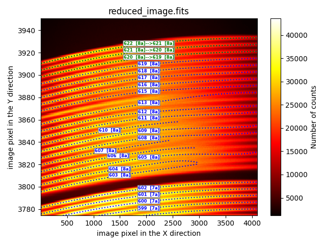
In the provided example, the traces of 3 fibers (numbers 620, 621, and 622) are
renumbered by subtracting 1 from the fiber number. The fibid_shift tag
can only be set to -1 or +1. It is important to note that the renumbered traces
all belong to fibers within the same box (8a in this particular case).
Fixing multiple traces at once
Bringing together all the corrections
In practical scenarios, it is common to need to fix multiple traces within a single image. As an example, let’s revisit the case of the image shown below.
In such cases, it is convenient to gather the reconstruction of the traces that
require recalculation into a single YAML file. We can combine the different
strategies described in the previous section. In each case, it will be
necessary to include the typical YAML separator --- to indicate the
different sections of the file.
 1description: extrapolation_through_user_points
 2fibid: 603
 3xstart_reuse: 4
 4xstop_reuse: 2000
 5resampling: 20
 6poldeg: 5
 7xstart: 6
 8xstop: 4090
 9user_points:
10  - [3500, 3817.0]
11  - [4000, 3818.0]
12refit: False
13---
14description: extrapolation_through_user_points
15fibid: 604
16xstart_reuse: 4
17xstop_reuse: 2000
18resampling: 20
19poldeg: 5
20xstart: 6
21xstop: 4090
22user_points:
23  - [3500, 3823.2]
24  - [4000, 3824.2]
25refit: False
26---
27description: extrapolation_through_user_points
28fibid: 606
29xstart_reuse: 4
30xstop_reuse: 2000
31resampling: 20
32poldeg: 5
33xstart: 6
34xstop: 4090
35user_points:
36  - [3500, 3835.0]
37  - [4000, 3836.2]
38refit: False
39---
40description: sandwich
41fibid: 607
42fraction: 0.5
43neighbours: [606, 608]
44xstart: 6
45xstop: 4090
46---
47description: sandwich
48fibid: 610
49fraction: 0.5
50neighbours: [609, 611]
51xstart: 6
52xstop: 4090
53---
54description: extrapolation_through_user_points
55fibid: 613
56xstart_reuse: 4
57xstop_reuse: 2000
58resampling: 20
59poldeg: 5
60xstart: 6
61xstop: 4090
62user_points:
63  - [3500, 3878.1]
64  - [4000, 3878.6]
65refit: False
66---
67description: sandwich
68fibid: 614
69fraction: 0.5
70neighbours: [613, 615]
71xstart: 6
72xstop: 4090
If the previous transformations are saved into a file named healing.yaml,
we can apply all the transformations with a simple execution of the script
megaradrp-heal_traces:
(megara) $ megaradrp-heal_traces reduced_image.fits master_traces.json \
  --fibids \
  --healing healing.yaml \
  --updated_traces master_traces_healed.json \
  --bbox 1,4096,3775,3950 \
  --verbose
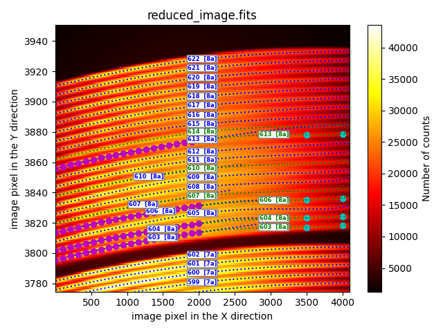
It is important to note that the script performs the calculation of the new
traces sequentially, allowing a previously repaired trace to be used in a
subsequent step. This behavior is exemplified by the fiber 606 in the provided
example. The trace of this fiber 606 is first reconstructed using the
extrapolation_through_user_points method. Subsequently, the obtained result
is reused to recalculate the trace of fiber 607 using the sandwich method,
which utilizes the new values of the trace of fiber 606 and the original trace
of fiber 608.
Important: final check
During the execution of megaradrp-heal_traces, we utilized the
parameter --updated_traces master_traces_healed.json, which
specifies the name of the JSON file containing all the corrected traces. It is
advisable to now employ this file in conjunction with the
megaradrp-overplot_traces script to perform a final verification and ensure
that all traces have been correctly corrected. This step is crucial since
improper configuration of the healing.yaml file could lead to undesired
outcomes.
(megara) $ megaradrp-overplot_traces reduced_image.fits master_traces_healed.json \
  --fibids \
  --bbox 1,4096,3775,3950
Please note that the second parameter is now master_traces_healed.json
instead of master_traces.json. We have successfully corrected all the
faulty traces, and the obtained result is satisfactory.
Warning
The newly created master_traces_healed.json file should now be copied to
its intended location within the calibration tree. When performing this
operation, it is advisable to rename the destination file to ensure that the
pipeline utilizes the corrected file (thereby overwriting the existing
master_traces.json file in the destination location, if applicable).
For example (assuming we are calibrating traces corresponding to the LR-R
VPH):
(for data obtained before February 2026)
(megara) $ cp master_traces_healed.json \
  ../calibrations/MEGARA/ca3558e3-e50d-4bbc-86bd-da50a0998a48/TraceMap/LCB/LR-R/master_traces.json
(for data obtained after February 2026)
(megara) $ cp master_traces_healed.json \
  ../calibrations/MEGARA/9f3fecbf-376c-47ae-a188-313b7d829104/TraceMap/LCB/LR-R/master_traces.json
The file master_traces_healed.json has a different uuid than the one
assigned to the file master_traces.json.
Obtaining traces for LR-U
It is challenging to obtain good traces for the VPH LR-U because the continuous lamp usually employed to obtain fiber-flat exposures does not provide enough signal in the bluest region of the spectrum. For this reason, the MegaraTraceMap recipe does not provide acceptable traces for this VPH.
In such cases, we can use a historical trace file for this VPH (for example the
file master_traces_LRU_20220325.json that can be downloaded from this link),
obtained from twilight exposures with sufficient signal, and transform the
location of these traces to match the fiber positions in fiber-flat (or
science) images corresponding to our observation campaign.
In general, simply applying a vertical offset to the initial traces in
master_traces_LRU_20220325.json will not be sufficient because we might
achieve a good fit for the first fibers (those appearing at the bottom of the
detector) but not for the last fibers (those appearing at the top). In this
case, we can use the fact that the global_offset parameter of the
megaradrp-heal_traces script accepts not only a real number but also
several numbers, which represent the coefficients of a polynomial
transformation that applies a slightly different vertical offset to each fiber.
For example, the following code applies a vertical offset following a
polynomial of the form \({\rm vertical\_offset} = 8.9 + 0.00060 \times y\),
where \(y\) is the vertical coordinate (along NAXIS2) of the considered
fiber, evaluated at the reference column (key ref_column in the JSON master
traces files, which is typically set to 2000, the middle location along the
wavelength axis, NAXIS1). The offset is calculated in pixel units.
(megara) $ megaradrp-heal_traces \
  reduced_image.fits \
  master_traces_LRU_20220325.json \
  --global_offset 8.9 0.00060 \
  --updated_traces master_traces_LRU_20220325_healed.json
The execution of this command opens a graphical window that, with the help of
the zoom button, allows us to easily verify how well the numerical coefficients
used for the --global_offset parameter work. Through trial and error, it is
possible to refine these numbers until the desired result is achieved.
Note that the above command does not apply any of the strategies described in
the previous subsection to try to correct individual fibers. That is, we are
not using any file of the type healing.yaml. We are simply applying a
different vertical offset to each fiber.
The file master_traces_LRU_20220325_healed.json will contain the
resulting master traces after applying the mentioned mathematical
transformation.
The newly created JSON file should now be copied to its intended location
within the calibration tree (remember to rename the destination file as
master_traces.json to avoid having several files in the same calibration
subdirectory; see warning note in the previous subsection).