Introduction
Scope
The goal of this document is to guide any potential user of the MEGARA instrument in its data processing, from the raw data provided by the GTC to wavelength- and flux-calibrated scientific-valid data. The MEGARA data processing described in this document will be done using the MEGARA Data Reduction Pipeline (DRP) which is available through github at https://github.com/guaix-ucm/megaradrp.
MEGARA instrument
MEGARA (Multi-Espectrógrafo en GTC de Alta Resolución para Astronomía) is a fiber-fed spectrograph with both Integral-Field (IFU) and Multi-Object (MOS) capabilities that was installed and commissioning at the 10.4m GTC telescope in the Spring of 2017. Since semester 2018B, MEGARA is available to the GTC community (Spain, Mexico and UF) in its two modes (LCB and MOS). The reader is referred to Gil de Paz et al. (2020, submitted) for more details.
The MEGARA IFU, which is called Large Compact Bundle (LCB hereafter), covers a field of 12.5 x 11.3 arcsec2 using 567 hexagonal spaxels of 0.62 arcsec in size plus 56 sky spaxels of equal size distributed in 8 bundles of 7 fibers distributed in the outskirts of the field at about 2 arcmin from the center of the LCB. The MOS makes use of a set of 92 robotic positioners each hosting a minibundle of 7 spaxels also of 0.62 arcsec in size each spaxel. These can patrol overlapping circular regions of 28 arcsec in diameter. These robotic positioners a distributed in a square region of 3.5 x 3.5 arcmin2, which roughly corresponds to the flat and non-vignetted focal plane of GTC at its Folded-Cassegrain F (FC-F) focus (see Figure 1). The MOS can be reconfigured starting from a list of target potions in matter of roughly a minute to a few minutes, depending on the level of number of overlapping patrol areas to be explored in a given configuration.
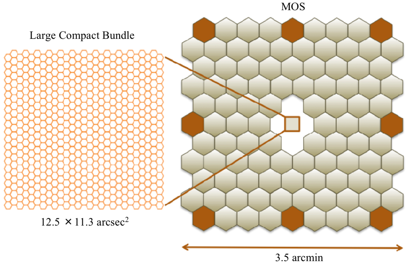
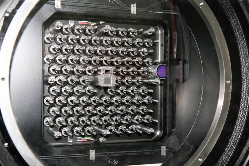
Figure 1: LCB and MOS in the focal plane of MEGARA at the Folded-Cass F focus of GTC. Left: Layout of the monolithic microlens array of the LCB placed at the optical axis of the instrument. Center: Hexagons representing the patrol areas of the 92 robotic positioners of the MEGARA MOS (in light grey) along with the positions of the eight sky bundles that are mounted along the LCB pseudo-slit (in orange). Note that the actual patrol areas are overlapping circular regions of 28 arcsec in diameter, while the distance between adjacent positioners is 24.5 arcsec. Right: MEGARA focal plane before the field lens was installed at the Laboratorio de Instrumentación Científica Avanzada (LICA-UCM) laboratory.
Both the LCB and the MOS along with other subsystems (focal-plane cover, Folded-Cassegrain rotator adapter, etc.) are located at the FC-F focus of GTC. The 623 (567+56) fibers of the LCB and the 644 fibers of the 92 robotic positioners of the MOS are routed through from the FC-F rotator to the Nasmyth A platform following a 44.5m-long path until they reach the MEGARA spectrograph. The MEGARA spectrograph is a fixed-angle (68º) collimator-camera system that is fed by two interchangeable curved pseudo-slits (LCB/MOS). The collimator is an all-refractive F/3 system composed by 5 lenses (1 aspheric singlet and 2 doublets) while the also all-refractive camera is composed by 7 lenses (two doublets, one with a CaF2 lens, and 3 singlets). In between collimator and camera, the spectrograph pupil can host different types of Volume-Phase Holographic (VPH) disperser elements, namely the low- (LR), mid- (MR), and high-resolution (HR) VPHs. Six LR VPHs cover the entire optical window at R=6,000, while 10 MR VPHs provide also full optical coverage but at R=12,000. Finally, the two HR VPHs allow observing in the \({\rm H}\alpha+[{\rm NII}]\) region and in the CaT region with R=20,000, although the optical design could in principle accommodate HR VPHs at any other optical wavelength. In Figure 2 we show the resolving power and spectral coverage for each VPH as measured during the integration and commissioning of the instrument. Note that in some of the cases the spectral coverage shown is shorter than the one actually achieved simply because the spectral lamp lacks bright spectral features (on which to measure the spectral resolution and resolving power), especially at the blue end of the optical spectral range.
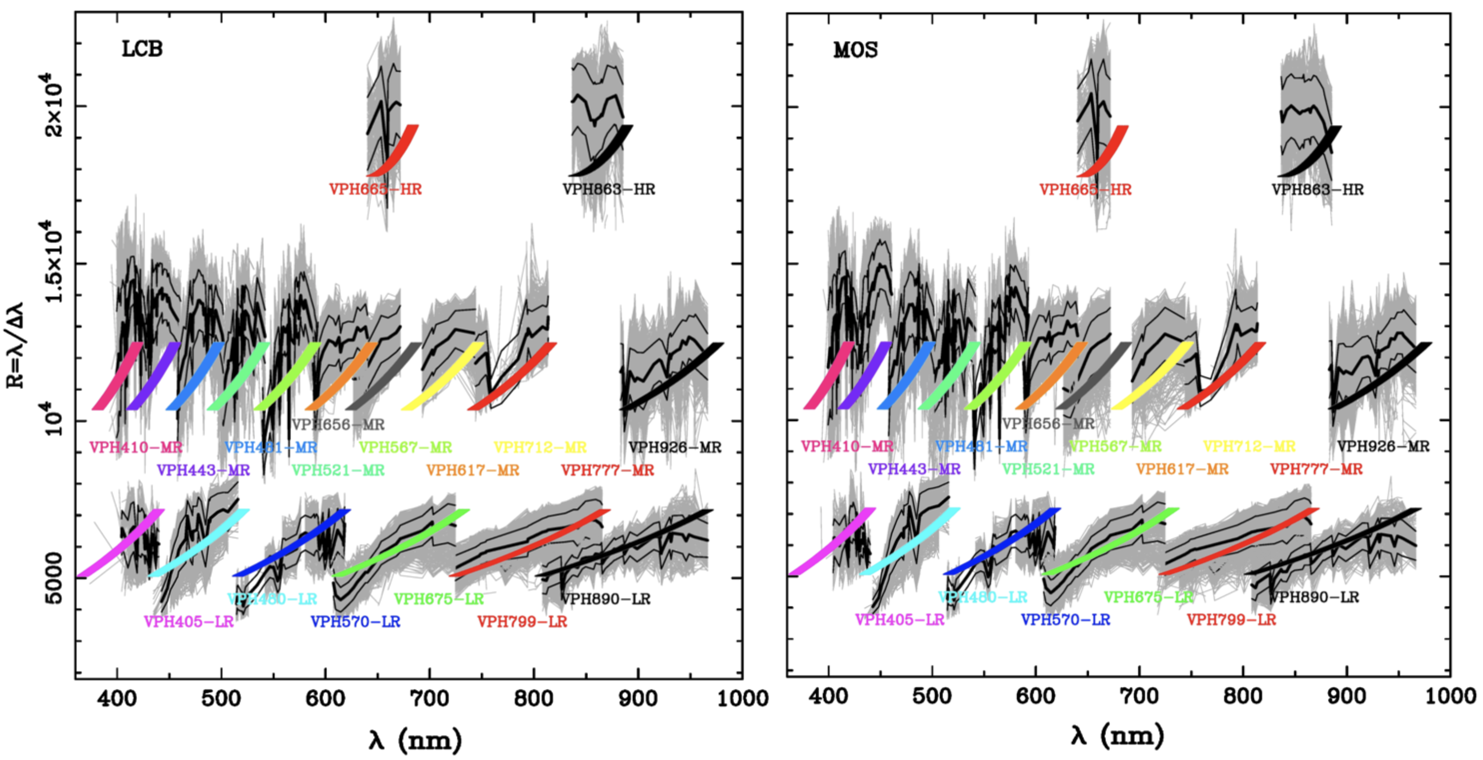
Figure 2: Plots showing the relation between resolving power \((R_{\rm FWHM})\) and wavelength coverage for all 18 MEGARA VPHs and for the LCB (left) and MOS (right) modes. Design values (colored lines) and measurements (grey lines that correspond to individual fiber spectra, while black thick and thin lines represent the mean and mean* \(\pm 1\sigma\) curves when all fiber spectra are used) are both shown.
The details on the different VPHs that can be used with MEGARA is given in Table 1. This table also includes the reciprocal (linear) dispersion (CDELT) and wavelength for the initial pixel (CRVAL for CRPIX=1) as adopted for the MEGARA DRP for different VPHs. The user is referred to different publications to learn more about the MEGARA instrument, including Gil de Paz et al. (2016), Gil de Paz et al. (2018) and Carrasco et al. (2018).
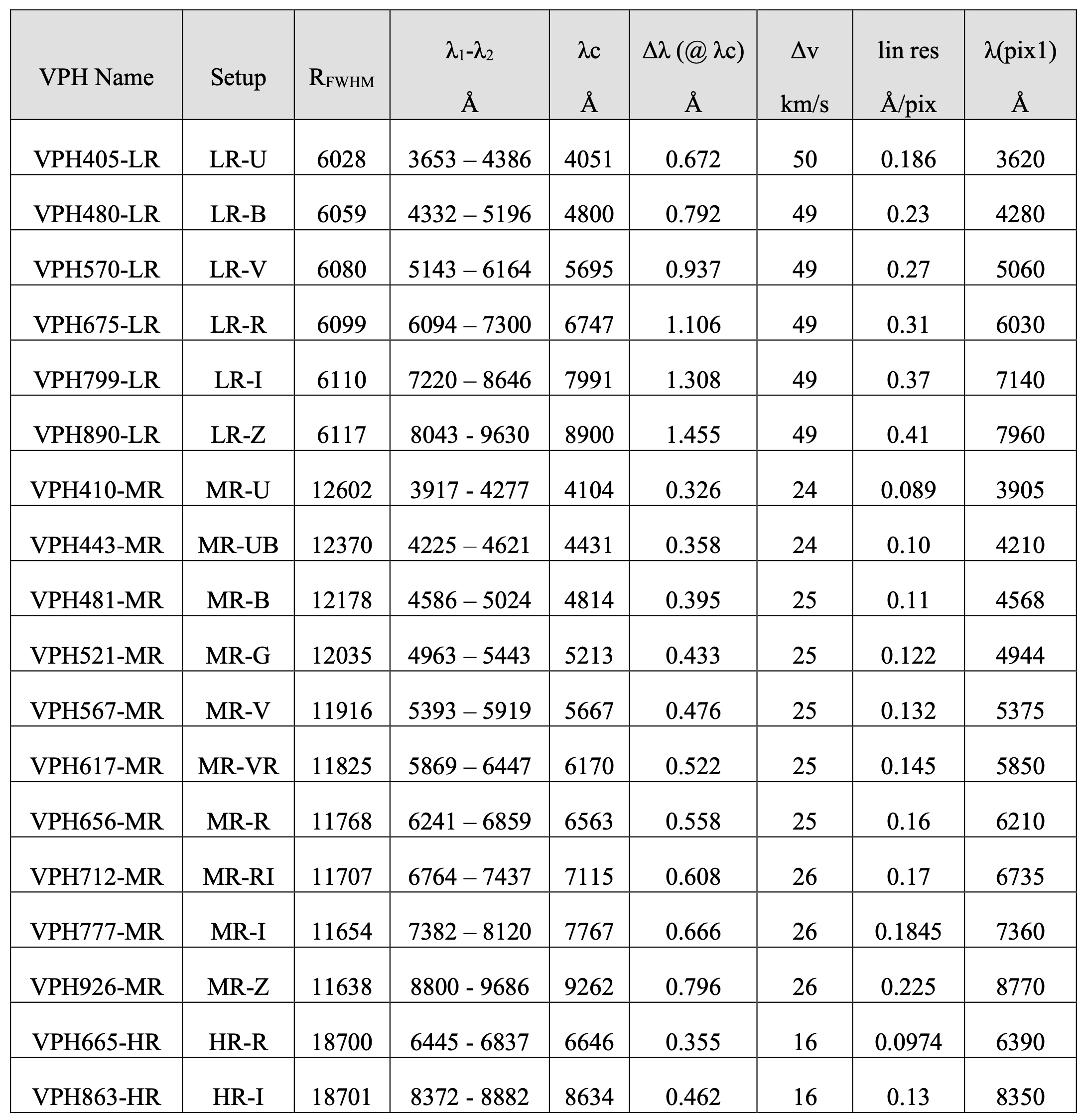
Table 1: MEGARA VPHs: scientific requirements (The resolution, \(R_{\rm FWHM}=\lambda/\Delta\lambda_{\rm FWHM}\), is derived from the FWHM \((\Delta\lambda_{\rm FWHM})\) of the 1D spectra). The values of the linear reciprocal dispersion and the wavelength of pixel 1 correspond to the linear solution implemented in the MEGARA DRP after the images are wavelength calibrated.
Note that the reciprocal dispersion is the one used for the linear solution in the images processed by the MEGARA Data Reduction Pipeline.